antenna_pattern
- antenna_pattern … end_antenna_pattern
antenna_pattern <pattern-name>
   <pattern-type-name>
      Common Commands
      ... Available Antenna Patterns Commands ...
end_antenna_pattern
Overview
antenna_pattern is used in transmitter and receiver commands to define the gain of an antenna for communication and sensor devices.
<pattern-name> Specifies the name of the antenna pattern.
<pattern-type-name> Specifies one of the Available Antenna Patterns:
Common Commands
The following commands can be used in any of the antenna pattern definitions:
- minimum_gain <db-ratio-value>
The minimum gain that will be returned.
Default: -300 db
- gain_adjustment <db-ratio-value>
An adjustment factor to be applied to the raw gain. This is especially useful if one wants to reuse a pattern that has been defined by a file (such as the Azimuth/Elevation Table) and simply scale the definition.
Default: 1.0 (no adjustment)
Note
This gain_adjustment AND gain_adjustment_table can be used together. The results are additive in logarithmic space (multiplicative in linear space).
- gain_adjustment_table … end_gain_adjustment_table
This command provides the means to define a frequency-dependent adjustment to the gain. The points define a curve on a plot whose x-axis is the log_10 of the frequency and the y-axis is adjustment factor in dB. Linear interpolation is used to derive the values for intermediate frequencies. Signals whose frequencies are outside the range of the table use the value from the appropriate endpoint (i.e., extrapolation is not performed).
The format of the table is:
gain_adjustment_table
   frequency <frequency-value> <db-ratio-1>
   frequency <frequency-value> <db-ratio-2>
   ...
   frequency <frequency-value> <db-ratio-n>
end_gain_adjustment_table
The following rules must be observed:
The entries must be in order monotonically increasing frequency.
There must be at least two entries, except that if no entries are provided then it is treated as though the table is not provided.
Note
This gain_adjustment AND gain_adjustment_table can be used together. The results are additive in logarithmic space (multiplicative in linear space).
Available Antenna Patterns
Azimuth/Elevation Table
antenna_pattern <pattern-name>
   pattern_table
      # Azimuth-Elevation Table Definition

      azimuth_beamwidth <angle-value>
      elevation_beamwidth <angle-value>

      # Common Commands

      minimum_gain <db-ratio-value>

      gain_adjustment <db-ratio-value>
      gain_adjustment_table ... end_gain_adjustment_table
end_antenna_pattern
Defines a pattern using any of the standard Azimuth-Elevation Table Definition formats.
- azimuth_beamwidth <angle-value>
Defines the width of the beam in azimuth.
Default: none - must be provided
- elevation_beamwidth <angle-value>
Defines the width of the beam in elevation.
Default: none - must be provided
Uniform or Constant Pattern
antenna_pattern <pattern-name>
   uniform_pattern
      peak_gain <db-ratio-value>
      azimuth_beamwidth <angle-value>
      elevation_beamwidth <angle-value>

      # Common Commands

      minimum_gain <db-ratio-value>
      gain_adjustment <db-ratio-value>
      gain_adjustment_table ... end_gain_adjustment_table
end_antenna_pattern
Defines a pattern whose gain is the peak_gain within the specified beamwidth limits and minimum_gain everywhere else.
- peak_gain <db-ratio-value>
Defines the peak gain of the antenna referenced to a perfect isotropic antenna.
Default: 1 db
- azimuth_beamwidth <angle-value>
Defines the width of the beam in azimuth.
Default: 180 deg
- elevation_beamwidth <angle-value>
Defines the width of the beam in elevation.
Default: 90 deg
Circular sine(x)/x Pattern
antenna_pattern <pattern-name>
   circular_pattern
      peak_gain <db-ratio-value>
      beamwidth <angle-value>

      # Common Commands

      minimum_gain <db-ratio-value>
      gain_adjustment <db-ratio-value>
      gain_adjustment_table ... end_gain_adjustment_table
end_antenna_pattern
Defines a sine(x)/x pattern with circular symmetry.
- peak_gain <db-ratio-value>
Defines the peak gain of the antenna referenced to a perfect isotropic antenna.
Default: 1 db
- beamwidth <angle-value>
Defines the half-power beamwidth (The angle subtended by points at which the gain becomes one-half the peak gain).
Rectangular sine(x)/x Pattern
antenna_pattern <pattern-name>
   rectangular_pattern
      peak_gain <db-ratio-value>
      azimuth_beamwidth <angle-value>
      elevation_beamwidth <angle-value>

      # Common Commands

      minimum_gain <db-ratio-value>
      gain_adjustment <db-ratio-value>
      gain_adjustment_table ... end_gain_adjustment_table
end_antenna_pattern
Defines a sine(x)/x pattern where the azimuth and elevation beamwidths do not have to be the same.
- peak_gain <db-ratio-value>
Defines the peak gain of the antenna referenced to a perfect isotropic antenna.
Default: 1 db
- azimuth_beamwidth <angle-value>
Defines the half-power beamwidth in azimuth (The angle subtended by points at which the gain becomes one-half the peak gain).
- elevation_beamwidth <angle-value>
Defines the half-power beamwidth in elevation (The angle subtended by points at which the gain becomes one-half the peak gain).
Cosecant Pattern
antenna_pattern <pattern-name>
   cosecant_squared_pattern
      peak_gain <db-ratio-value>
      azimuth_beamwidth <angle-value>
      elevation_beamwidth <angle-value>
      minimum_elevation_for_peak_gain <angle-value>
      elevation_of_peak/csc2_boundary <angle-value>
      maximum_elevation_for_csc2 <angle-value>

      # Common Commands

      minimum_gain <db-ratio-value>
      gain_adjustment <db-ratio-value>
      gain_adjustment_table ... end_gain_adjustment_table
end_antenna_pattern
Defines a antenna pattern that will:
Use a sin x/x pattern for elevation angles less than minimum_elevation_for_peak_gain.
Use the peak gain from [ minimum_elevation_for_peak_gain, elevation_of_peak/csc2_boundary ]
Use a csc^2 pattern from [ elevation_of_peak/csc2_boundary, maximum_elevation_for_csc2 ]
Use a sin x/x pattern for angles above maximum_elevation_for_csc2.
- peak_gain <db-ratio-value>
Defines the peak gain of the antenna referenced to a perfect isotropic antenna.
Default: 1.0 db
- azimuth_beamwidth <angle-value>
Defines the half-power beamwidth in azimuth (The angle subtended by points at which the gain becomes one-half the peak gain). This is used to the determine the azimuth-dependent portion of the gain.
- elevation_beamwidth <angle-value>
Defines the half-power beamwidth in elevation (The angle subtended by points at which the gain becomes one-half the peak gain). This is used to determine the elevation-dependent port of the gain when the elevation angle is above or below the cosecant_squared region.
- minimum_elevation_for_peak_gain <angle-value>
Defines the minimum elevation angle for the peak_gain value.
Note
A non-zero value result in issues for radars which slew or scan using a non-peak gain at 0 degrees, i.e. the elevation cueing/scanning angle.
- elevation_of_peak/csc2_boundary <angle-value>
Defines the elevation angle for the peak cosecant-squared boundary value.
- maximum_elevation_for_csc2 <angle-value>
Defines the maximum elevation angle for the peak_gain value.
Electronic Steered/Scanned Array (ESA) Pattern
antenna_pattern <pattern-name>
   esa_pattern
      debug
      element_spacing_x <length-value>
      element_spacing_y <length-value>
      length_x <length-value>
      length_y <length-value>
      number_elements_x <integer-value>>
      number_elements_y <integer-value>>

      amplitude_quantization_bits <integer-value>>
      phase_quantization_bits <integer-value>>
      failed_elements_ratio [0.0 .. 1.0]

      element_pattern <pattern-name>
      back_baffled <boolean-value>
      lattice <lattice-type>
      distribution_type <distribution-type> ...

      # Common Commands

      minimum_gain <db-ratio-value>
      gain_adjustment <db-ratio-value>
      gain_adjustment_table ... end_gain_adjustment_table
end_antenna_pattern
The electronic steered/scanned array antenna pattern generator is an MxN array defined in the x-y plane (x is in the azimuth direction, y is in the elevation direction).
Note
Beam steering loss is accounted for by default and can be modified by the input commands provided for in the Antenna Commands section.
Note
This antenna pattern is generated by looping over all the elements to get each elements contribution and phasing information and then summed, causing it to have an N^2 computation time and may not be suited for applications where time is a critical component (e.g., real-time simulation application/exercise).
- debug
Turn debug on.
Default: false
- element_spacing_x <length-value>
The horizontal element spacing for the array. Requires number_elements_x OR length_x to be defined.
- element_spacing_y <length-value>
The vertical element spacing for the array. Requires number_elements_y OR length_y to be defined.
- length_x <length-value>
The total horizontal array length. Requires number_elements_x OR element_spacing_x to be defined.
- length_y <length-value>
The total vertical array length. Requires number_elements_y OR element_spacing_y to be defined.
- number_elements_x <integer-value>
The number of individual elements in the horizontal direction of the array. Requires length_x OR element_spacing_x to be defined.
- number_elements_y <integer-value>
The number of individual elements in the vertical direction of the array. Requires length_y OR element_spacing_y to be defined.
- amplitude_quantization_bits <integer-value>
The number of bits used to quantize the amplitude response of each element in the array. The reference value is set to an amplitude of 1.
- phase_quantization_bits <integer-value>
The number of bits used to quantize the phase response of each element in the array. The reference value is set to 2*pi radians (360 degrees).
- failed_elements_ratio <real-value>
The ratio of failed elements in the array.
Note
Actual failed elements are randomly selected during simulation initialization for each pattern instance in the simulation and used throughout the simulation.
Default: 0.0
- element_pattern <pattern-name>
Specifies the element pattern, via an antenna_pattern name, for all elements in the array.
Note
The element pattern is expected to be relative to an isotropic element (i.e., dBi - normalized to 1.0 (0.0 dB).)
Note
It may be necessary to set the electronic_beam_steering_loss_exponent to 0.0 in order to negate any effect this has on the off boresight gain if already accounted for in the element pattern.
Default: isotropic element assumed
- back_baffled <boolean-value>
Specifies whether the antenna elements are back baffled for azimuth angles outside [-90 90] degrees.
Note
If this value is set to true and the minimum_gain was specified it will be used for values outside [-90 90] degrees for the gain.
Note
If this value is set to true and the minimum_gain was not specified -300 dB will be used outside [-90 90] degrees for the gain.
Note
If this value is set to false the element gain will be used, 0.0 dB for isotropic and actual gain if element_pattern is specified for the gain.
Default: true
- lattice <lattice-type>
The lattice type to be used to define the element locations. Types are as as follows:
rectangular A rectangular lattice will be used with all elements inline in rows/columns.
triangular A triangular lattice will be used where the corresponding rows are offset by one half the ‘element_spacing_x’.
Default: rectangular
- distribution_type <distribution-type>
The weighting distribution to apply, available distributions are:
uniform Apply an uniform distribution among the array elements.
- taylor Apply a Taylor distribution among the array elements.
Additional required inputs:
- sidelobe_level_x <db-ratio-value>
The sideobe level in the x-direction of the array in the range of 15 dB to 55 dB.
- sidelobe_level_y <db-ratio-value>
The sideobe level in the y-direction of the array in the range of 15 dB to 55 dB.
- n_bar_x <integer-value>
The number of bars in the x-direction of the array in the range of [1, 2, …].
- n_bar_y <integer-value>
The number of bars in the y-direction of the array in the range of [1, 2, …].
Default: uniform
ALARM Antenna Pattern File
antenna_pattern <pattern-name>
   alarm_pattern
      file <file-name>
      gain_correction <db-ratio-value>

      # Common Commands

      minimum_gain <db-ratio-value>
      polarization  [horizontal|vertical|default]
      gain_adjustment <db-ratio-value>
      gain_adjustment_table ... end_antenna_pattern.gain_adjustment_table
   end_alarm_pattern
end_antenna_pattern
Defines a pattern using an ALARM antenna pattern definition file.
- file <file-name>
The name of the file containing the antenna pattern definition. file_path processing will be applied to the value.
- gain_correction <db-ratio-value>
An synonym for the gain_adjustment command.
- polarization [horizontal|vertical|default]
Provide a polarization to match one or more polarizations specified in the antenna pattern file. This input is only necessary if polarizations are specified in the antenna pattern file; otherwise it should be omitted.
GENAP Pattern
antenna_pattern <pattern-name>
   genap_pattern
      peak_gain <db-ratio-value>
      aperture_shape [ rectangular | elliptical | circular ]
      azimuth_distribution [ uniform | cosine | bw/sll ]
      azimuth_beamwidth <angle-value>
      azimuth_exponent [ 1 .. 4 ]
      azimuth_side_lobe_level <db-ratio of 15 db to 55 db>
      elevation_distribution [ uniform | cosine | bw/sll | cosecant ]
      elevation_beamwidth <angle-value>
      elevation_exponent [ 1 .. 4 ]
      elevation_side_lobe_level <db-ratio of 15 db to 55 db>
      elevation_cosecant_limit <angle-value>
      elevation_beamwidth <angle-value>

      # Common Commands

      minimum_gain <db-ratio-value>
      gain_adjustment <db-ratio-value>
      gain_adjustment_table ... end_gain_adjustment`table
end_antenna_pattern
The general antenna GENAP pattern is derived from the Technical Radar Analysis and Modeling TRAMS radar analysis system. It allows definition an antenna pattern using several different methods.
Complex Electronic Steered/Scanned Array Pattern
This is an extension to the base Electronic Steered/Scanned Array (ESA) Pattern to include edge angle modifications and array subdivision for multiple beamforming applications requiring array subdivision.
antenna_pattern <pattern-name>
   complex_esa_pattern
      ... Base ESA Commands ...
      ... Common Commands ...

      edge_angle_x <angle-value>
      edge_angle_y <angle-value>
      array_subdivision_table ... end_subdivision_table
end_antenna_pattern
The complex electronic steered/scanned array antenna pattern is an MxN array defined in the x-y plane (x is in the azimuth direction, y is in the elevation direction).
Note
Beam steering loss is accounted for by default and can be modified by the input commands provided for in the Antenna Commands section.
Note
This antenna pattern is generated by looping over all the elements to sum each element’s contribution and phasing information. Therefore it has an N^2 computational complexity and may not be suitable when performance is a concern, for example in applications with realtime constraints.
Edge Angle Pictorial Description
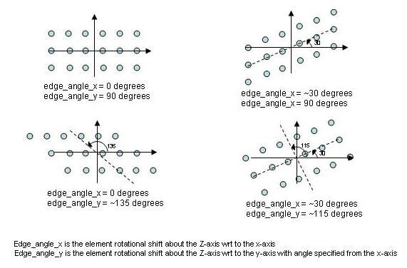
- edge_angle_x <angle-value>
The element rotational shift about the Z-axis with respect to the x-axis. See Edge Angle Pictorial above.
Default: 0 degrees
- edge_angle_y <angle-value>
The element rotational shift about the Z-axis with respect to the y-axis with angle specified from the x-axis. See Edge Angle Pictorial above.
Default: 90 degrees
- array_subdivision_table … end_array_subdivision_table
This block defines the X and Y subdivision ratios as a function of the beam count. When the system has multiple beams defined then the array is subdivided per the ratios in the table. Format is as follows:
array_subdivision_table
   beam_count 1 <x-ratio> <y-ratio>
   beam_count 2 <x-ratio> <y-ratio>
   ...
   beam_count N <x-ratio> <y-ratio>
end_array_subdivision_table
- beam_count <beam-count-integer-value> <x-ratio> <y-ratio>
Specifies the beam count and ratios to apply in the x & y direction respectively. The array length and/or number of elements will be divided by this ratio. The <beam-count-integer-value> should be in the range [1, 2, .., N] in increasing order. The ratios must be greater than 0.0 and less than or equal to 1.0 .
Note
Currently this functionality is only available in WSF_RF_JAMMER systems with multiple beams defined.
Note
A value for each beam count that the system can create should be accounted for in the ‘beam_count’ table.
Default: No array subdividing
Element Electronic Steered/Scanned Array (ESA) Pattern
This is an extension to the base Electronic Steered/Scanned Array (ESA) Pattern to allow for input of the element locations and associated distribution weightings of each element.
antenna_pattern <pattern-name>
   element_esa_pattern
      ... Base ESA Commands ...
      ... Common Commands ...

      aperture_efficiencies <efficiency-value-x real-value> <efficiency-value-y real-value>
      aperture_efficiency <real-value>
      average_element_spacing_x <length-value>
      average_element_spacing_y <length-value>
      element_locations ... end_element_locations
end_antenna_pattern
The element electronic steered/scanned array antenna pattern is a user-defined array in the [x, y, z] plane (x is in the azimuth direction, y is in the elevation direction and z is in the depth direction, per the right hand rule).
Note
Beam steering loss is accounted for by default and can be modified by the input commands provided for in the Antenna Commands section.
Note
This antenna pattern is generated by looping over all the elements to sum each element’s contribution and phasing information. Therefore it has an N^2 computational complexity and may not be suitable when performance is a concern, for example in applications with realtime constraints.
- aperture_efficiencies <real-value> <real-value>
Specifies the value for the aperture efficiencies for the horizontal and vertical (x-y) planes respectively, from 0 to 1.
Default: 1
- aperture_efficiency <real-value>
Specifies the single value for the aperture efficiency in the horizontal and vertical (x-y) plane from 0 to 1.
Default: 1
- average_element_spacing_x <length-value>
The average horizontal element spacing for the array. Requires number_elements_x OR length_x to be defined.
- average_element_spacing_y <length-value>
The average vertical element spacing for the array. Requires number_elements_y OR length_y to be defined.
- element_locations … end_element_locations
A list/table of the element locations and associated weight of the element. Formatting is as follows:
element_locations
  <element-location-x-1> <element-location-y-1> <element-location-z-1> <element-phi-1> <element-theta-1> <distribution-weighting-value-1>
  <element-location-x-2> <element-location-y-2> <element-location-z-2> <element-phi-2> <element-theta-2> <distribution-weighting-value-2>
  ...
  <element-location-x-N> <element-location-y-N> <element-location-z-N> <element-phi-N> <element-theta-N> <distribution-weighting-value-N>
end_element_locations
<element-location-x>, <element-location-y> and <element-location-z>: Each is length-value and specifies the element location with respect to the center of the array at (x,y,z) = (0,0,0).
<element-phi> and <element-theta>: Each is angle-value and are used in the calculation of the element normal direction from the array’s reference normal.
<distribution-weighting-value>: A real-value that specifies the distribution weighting value for the specified location/element. Similar to the distribution type of the base ESA pattern, but it is specified instead of calculated for this type of pattern.